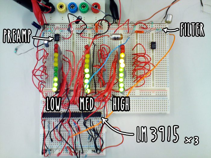

This VU meter circuit was my mini project for my first year university.
This post briefly goes over how I created a VU meter for monitoring loudness levels in an audio signal and displaying it visually using LEDs.
This is a pretty brief overview of how I went about creating this VU meter (VU = volume unit = loudness) but hopefully should give you an idea of how easily it can be done using the LM3915 display driver chip.
The first circuit I built used an array of comparators using op-amps (LM741) to switch the LEDs on at different voltages. I later found the LM3915 bar/dot display driver that will do this all in one package. If you want to learn more about comparators and op-amps then I recommend building this ‘long way round’ circuit. However, if you want a quick and easy circuit for your project then scroll down the ‘easy way’ using the LM3915.
Audio VU meter using op-amps
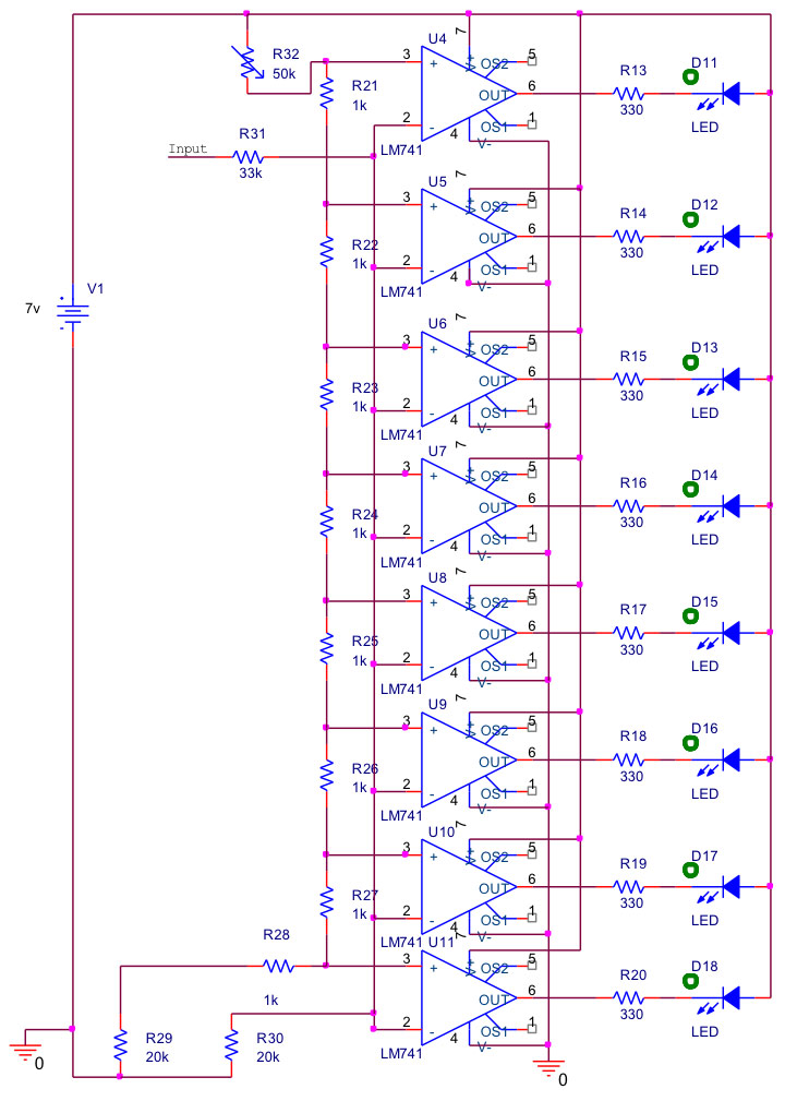
The circuit uses eight 1kΩ resistors to form a voltage divider to give each op-amp a set reference voltage. The voltage range can be adjusted by the 50KΩ potentiometer.
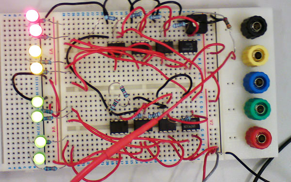
Then I discovered the LM3915 display driver chip
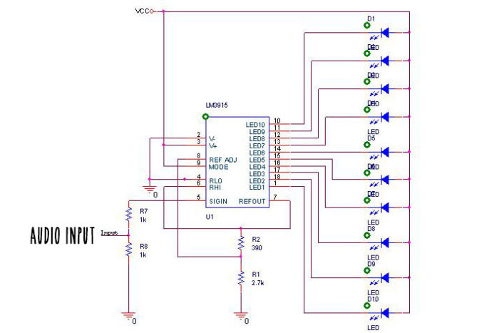
After some research I found out about the LM3915 integrated circuit- dot/bar display driver. The LM3915 is a monolithic integrated circuit that senses analogue voltage levels and can drive ten LEDs in 3/dB steps. It basically contains the previous op-amp circuit but has all the reference voltages all setup for logarithmic operation.
The datasheet gives several example circuits that can be used for many different applications. I built the audio power meter shown in the datasheet schematic below:
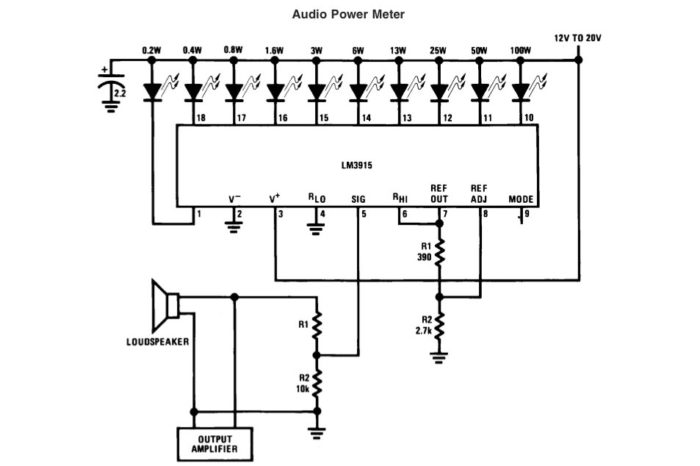
The LM3915 display driver circuit
LM3815 breadboard prototype

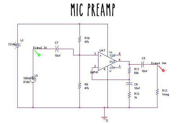
For a low level audio input, for example a microphone, an amplifier is needed before the input to the LM3915. I simulated and built the circuit below using an LM741:
Taking it further: 3 band VU meter using passive filters
I filtered the audio input into low, mid and high using RC (resistor capacitor) filters so that each band has its own VU meter.