

This post goes over the receive side of a home made microwave link system for audio applications. For the transmitter side go here: 10GHz X-band microwave link transmitter
Receiving the microwave ‘beam’ (from the microwave transmitter using a gunn diode) and getting back the originating AF (audio frequency) is pretty straight forward. Here’s what you need:
- Universal LNB (used for receiving analogue TV) – stands for Low-noise Blockdown Converter
- Satcan tuner
- A few passive components
- Cables
I’ll go through each of these now…
LNB
This is kind of like a complicated aerial that receives the 10GHz ‘beam’ and down-converts the frequency before going into the satcan via satellite coax cable (typically 75Ohms) terminated with F-connectors. Look for a universal LNB that receives frequencies between 9.75 and 10.60 GHz. The picture below shows a common (although rather old) Cambridge universal LNB, which seem to work very well.

Satcan tuner
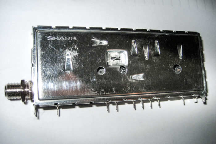
This is the main component in this system. These devices are used in TV satellite receiver boxes to demodulate the transmitted data (audio and video). I’m using a Sharp BSFA75G08 satcan tuner, as shown below.
Basically
The IF (intermediate frequency) is fed from the LNB into the satcan which will then demodulate the initial carrier, extracting the audio where it then gets amplified to bring it up to the correct levels. There are many different satcans out there and all have different pinout configurations which can be very hard to find and sometimes are kept secret by the manufacturer.
Sharp satcan wiring and circuit
In most cases the satcan will require a small external circuit which can usually just be soldered onto the pins with no extra PCB. The circuit usually just provides the right pins with the correct voltage using voltage regulators and also a few resistors and caps for audio and tuning. You may find that some satcans have a low audio output, in which case you will need to a basic op-amp or audio amplifier circuit.
The BSFA75G08 (below and above) requires 12v to operate (or at least 13.8V if using a 12V regulator). See the diagram below:
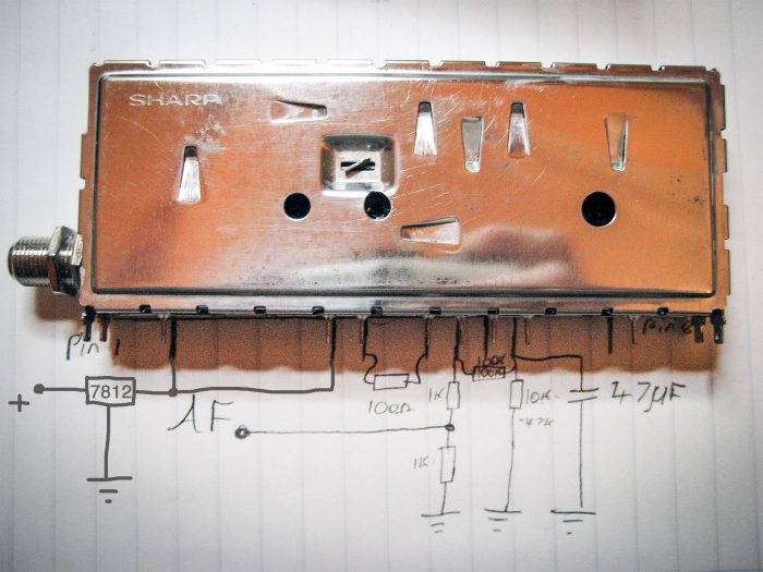
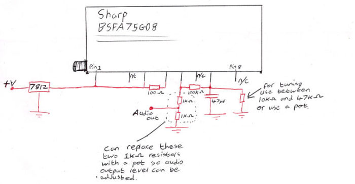
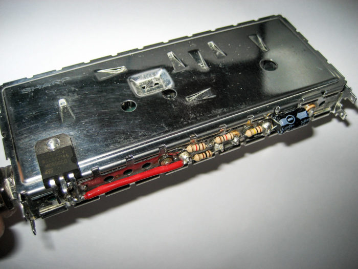
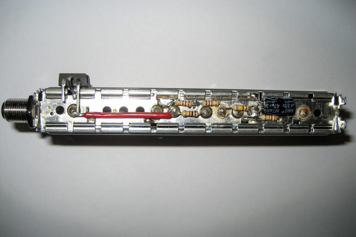
The wired satcan tuner
This is the wired satcan using the above circuit. Note that you can solder the voltage regulator to the case. This is now ready to use:
Cables
It is always best to use a screened type cable when dealing with audio (e.g linkbox to gunn module) However from the LNB to the satcan receiver a 75Ohm coax cable should be used, terminated with f-connectors.