

This is a complete FM transmitter (band 2: 88-108MHz) that runs from mains power and is boxed up in an aluminium case.
It uses an RF amplifier using the 2SC1971 transistor (see here: 8W RF amplifier circuit using the 2sc1971) driven by a 500mW PLL driver (see here: 1W PLL FM transmitter overview)
Inside a basic home-made FM transmitter
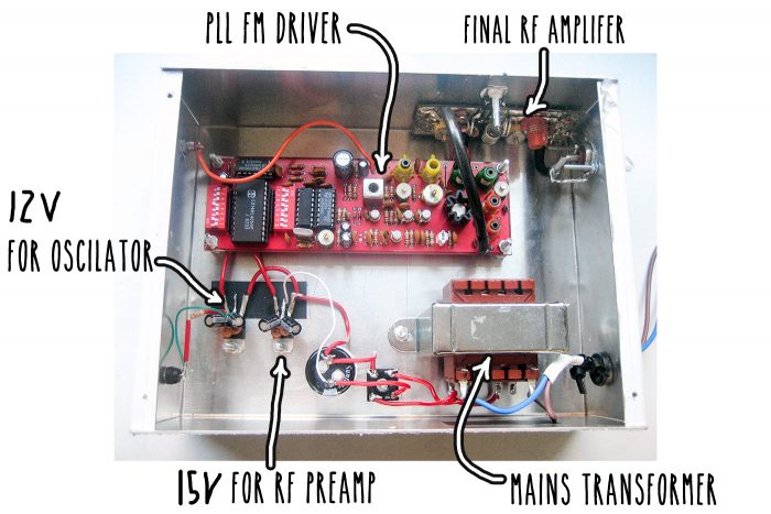
For the PSU i used:
2x12V mains chassis mount transformer (wired in parallel)
35V 4700µF electrolytic capacitor for smoothing
Bridge rectifier (nearly any will do)
1x 12V voltage regulator (7812) for the oscillator and PLL section of the driver (left half of the red board in the picture below)
1x 15V voltage regulator (7815) to power the pre-amplifer section of the driver (right side of the red board in the picture below)
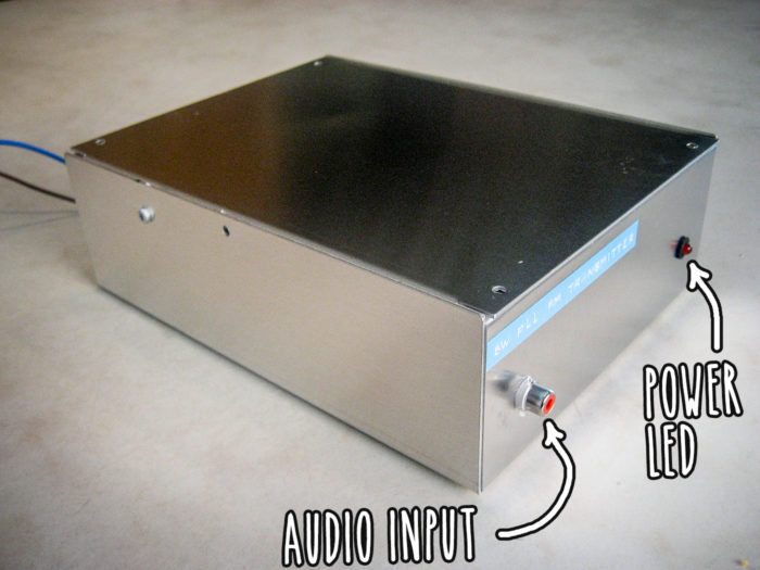
FM transmitter front panel
The design is as simple as possible. Audio is fed into the transmitter via the case mounted phono mono socket. Power is indicated with a red LED
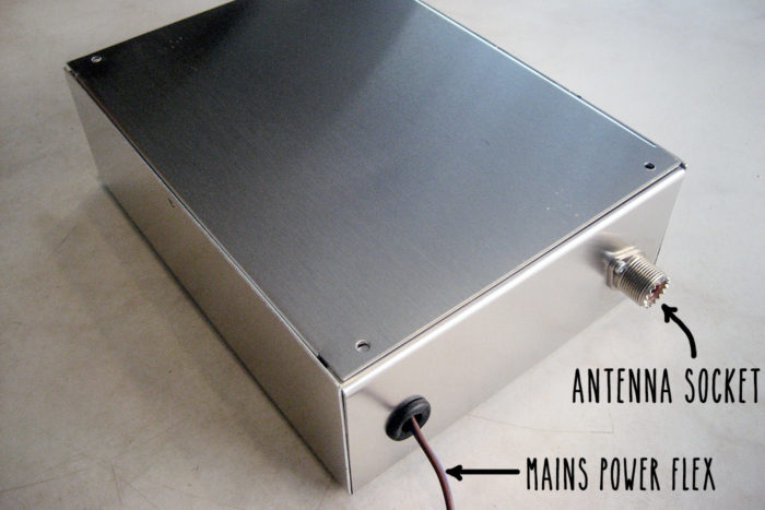
Fm transmitter rear
The rear of the box has a grommeted hole to take mains flex cable. The RF output of the transmitter is provided via an SO239 panel mounted socket. The load (antenna/aerial) should be 50Ohm. See this post for details on how to make an aerial: Dipole aerial for FM broadcast
I modified this later on by putting a microwave satcan receiver (see here: 10GHz X-band Microwave receiver for Audio) inside the case, so that audio can be sent to the transmitter from a remote location.
Some fucking guy
Heh…transmitter. what will they come up with next?