

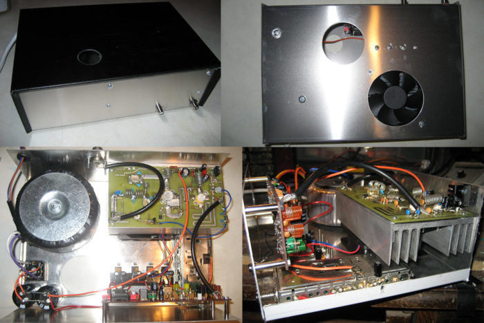
Here are some pictures of some of the steps for building an FM transmitter into an enclosure. The transmitter is PLL tuned via dip switches using a Dawson 1W PLL transmitter driver which drives a 150W FM amplifier. The amplifier uses a BLF244 mosfet into an SD1407. An 80mm fan is used directly underneath the amp heat-sink. This ‘rig’ is complete with power supply and microwave link receiver. It is compact, neat and powerful.
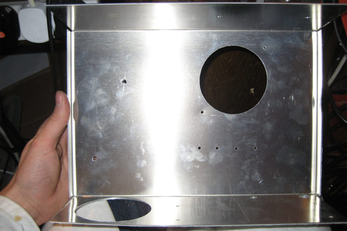
Prepare the aluminium enclosure
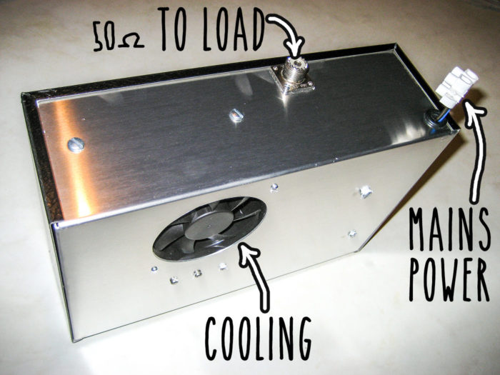
Drill holes and prepare the enclosure. I have used an aluminium case with vinyl effect lid from Maplins
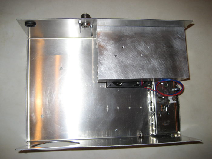
Fit fan, amplifier heatsink and satcan receiver
The first thing to go in the box is the 80mm fan and then the amp heat-sink on top. Screw the heatsink to the side of the box using large self tapping screws, drilling small pilot holes first for a guide. I fitted the microwave receiver at this point as it slots under the heatsink nicely. Birmingham Aluminium do some good heat-sinks to your size.
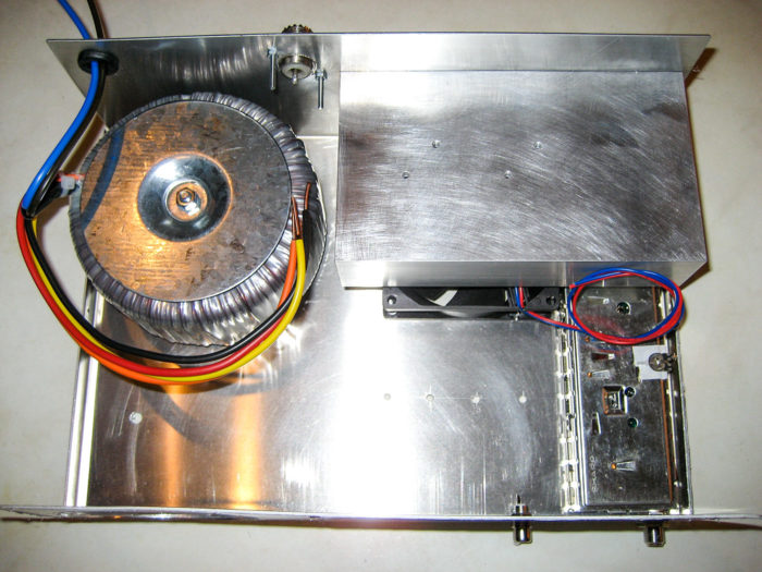
Fit toroidal transformer
I have used a 300VA toroidal transformer to power everything. Assuming 50% efficiency (absolute worst case), 300VA will easily suffice. 300/28V = 10.7A. Newmarket transmformers do some good custom transformers at the lowest price I’ve seen.
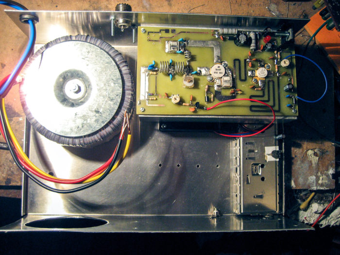
Amplifier circuit board
Here’s the 150W RF amp PCB fitted to the heat-sink. The two transistors sit nice and flat on the heat-sink (remember to use heat-sink compound). Do not over tighten the transistor flange screws as they will slightly expand as they heat up which can cause damage.
Power supply components
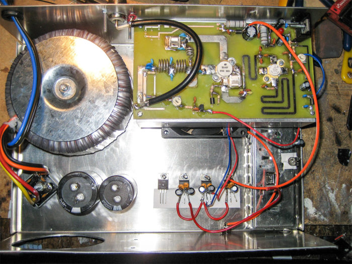
In goes the large smoothing capacitors for the PSU and also the individual voltage regulators.
FM PLL transmitter driver board
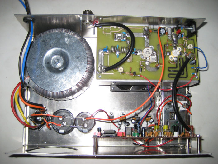
Finally the pll driver is fitted and connected up.
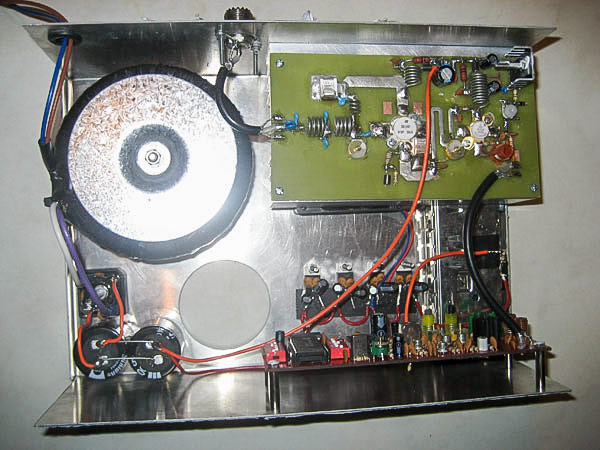
Here’s a variation
luke
im looking buy a full rig, my email is lucus_cdj@yahoo.co.uk