

Here’s my final year university project for my electronic and electrical engineering degree.
I explored the use of an FPGA for digitally processing audio in real time, as well as creating some common audio effects (in VHDL) – delay, reverb, filter, flanger etc. Scroll down to see it in action (video)…
This project could be the basis, and framework, to create pretty much any audio effect.
Project title: The design and realisation of an FPGA based audio processor
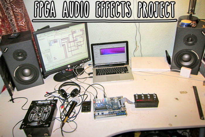
This is a super low latency digital audio effects processor using an FPGA and the Altera DE2 development board. The audio (guitar, mic, whatever) is connected to the input of the DE2 board to be digitised and processed according to what effect is selected. Everything is written in VHDL using Quartus II V11.0. New effects can be written in VHDL then converted to a block symbol and routed in to the existing system at the top level.
I made a rotary control box that interfaces dynamically with each effect block, depending on what is currently selected. The LED bar on the control box shows the value of parameter currently being adjusted (or the last one to be adjusted).
The project took 6 months in total and got me a decent mark for my degree. You can download my scanned notebook (with every single note I wrote down as I developed this project) and my full report in PDF format at the bottom of the page.
Latency is super low at less than 1ms. If you want to know how to use the Wolfson WM8731 CODEC on the Altera DE2 board (or any other FPGA development board) then hopefully this report will give you a massive head start. This took a while to get my head around.
I made a rotary encoder control box to have full control over all the effects and parameters within the VHDL code.
Report abstract…
Quartus II v11.0 and SOPC Builder have been used to design and create the VHDL code to be synthesised. The implementation of the VHDL design uses the DE2 development board from the Altera which is based around a Cyclone EP2C25 FPGA device having 35000 logic elements.
Four audio effects were explored and implemented: echo, flanger, filter and reverb. External control to the FPGA was implemented using rotary encoders to change various effect parameters and visual feedback been given through an LCD. The final design utilises a NIOS II soft-core processor to form part of the user interface. The results show that the total system latency of the FPGA audio processor was considerably less than a computer software application; less than 1ms compared to 10ms.
The initial concept has been proven using a total of 11702 logic elements. There is much scope for development of the final project. Future work could focus on a more user-friendly system in terms of the user interface and also the creation of more advanced audio effects.
See the audio effects in action
Download my full report and design notebook
Here’s the final report (PDF)
Here’s the final report that I handed in for my final year project of my electronics engineering degree: https://gum.co/fpga-audio-effects-final-year-project-mike-hudson
My scanned notebook (PDF):
I kept a notebook of all my design notes, ideas, sketches, problems and solutions: https://gum.co/fpga-audio-processor-final-year-notebook
Jack Tranckle
Hi Mike, would it be possible to get a copy of your report? the links seems to not be working. thanks!
Alexander Pruss
This is just another request whether you would be able to release the code. Thanks!
Baran Öztürk
Hey Mike,
I’m trying to build some sort of “freeze” pedal (like sustain pedal but it loops endlessly) for my senior project, I don’t know if it would be so much to ask your code but at least can you share a link for your report? It would be very helpful.
Thank you!
André Fonseca
Hello there!
I am currently in a project doing a “guitar pedal” with the FPGA, the concept is very much like what you have done. Is there any chance you can provide your report and code?
mimin
Where is the download link for your report?
Ahmad Abdullah
hi mike, any chance i can get your codes? i have similiar project that include buffering, really need help on how to use memory for buffering. It would really help, thank you.
ahmed.shalahuddin@gmail.com
Daniel Stelian Dobre
Hello, its an interesting project. Can you share the code ? Thank you
Muhammad Shahab
The abstract says that the latency of this FPGA system is 1ms. How did you measure the latency?
priya
Hii mike..im priya..working with the concept of your project..can u send me ur project code?..as it gives some idea for me..if possible reply me soon..
Derek Charles Cabrera Judilla
Hi mike! any chance you can send me your codes? i’m trying do make fpga implemented 5 band grahpic equalizer for my thesis the only difference from my equalizer is that the filters will be in the switches does can be manipulated when its logic 1 and push buttons will be my +/- gain..also in your line out does it go directly to the speaker or it passes through first in an amplifier? email me your codes and hopefully your techniques on verifying your design wheter you use spectrume analyzer and oscilloscope..derek_judilla@yahoo.com
Cristiano Lacerda
Any chance relasing your vhdl code as open soruce?
Mike Hudson
Yeah I will do at some point but it wont be any time soon simply because I’m on the road travelling and that stuff is on a HD in England. Thanks for your interest though… How are you getting on?
mustafa
hi
i know you are too busy
but could you please tell me if there is an analogue to expansion conneceter Adapter ???
the purpose is to get an analogue audio and put it to the expansion connecter of the fpga
Mike Hudson
Hi, I’m sure what you mean exactly, analogue to expansion connector adaptor?
David Kester
Hey mike,
I am working on a project, were we want to make a digital MIDI synth, right now the system works fine, but after 20 secs the serial to parallel converter (uart) crashes. Do you have any tips in order to better implement this module?
We would greatly appreciate it.
David
Mike Hudson
Hi, i’ve pretty much already done it using a state variable filter – this gives LP, BP and HP. So that could be adapted. To answer your question, not hard. The hardest part of this was writing/reading to the RAM for long delays (long as in a few thousand samples – milliseconds)
Wink Wonder
Greetings. How hard would it be to program this for a 3-band equalizer?