

For a project in the last year of my National Diploma I decided to design and prototype a function generator, with multiple waveform selection and a frequency readout display. This is just some cut down bits from my full report- Let me know if you want a copy complete with schematics.
Using the XR2206 (function generator IC)
The block diagram below shows the internal workings of the XR2206 in the form of a block diagram. Essentially the chip contains A VCO (voltage controller oscillator), wave shaper and buffer.
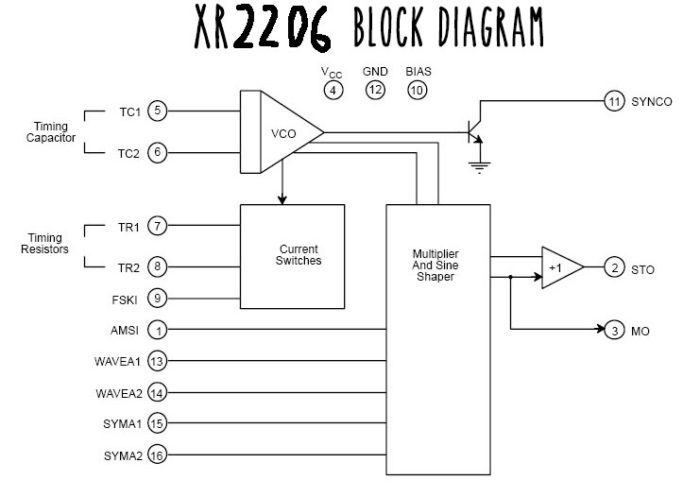
The frequency of the VCO is set with a capacitor and a resistor. The capacitor sets the frequency range whilst a variable resistor can be used to vary the frequency in the set range. The frequency is defined by ƒ = 1/(RC). For a starting point for the design of the frequency generator I used the test circuit from the XR2206 datasheet. I built this on bread board and experimented with the timing resistor and capacitor and managed to get the frequency up to 4MHz which was surprising since the datasheet quotes max frequency up to 1MHz. I eliminated things I didn’t need such as the FSK input and also R2 which is only needed for the FSK function. At this point I realised the square wave output is separate to the sine and triangle waves and is not fed through the wave shaping circuit or the output buffer. Since the amplitude is adjusted using the output buffer in the XR2206, the
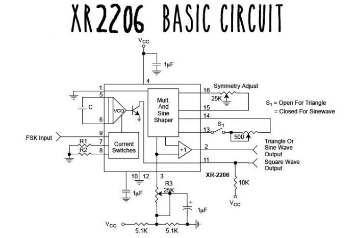
amplitude of the square wave cannot be adjusted along with the sine and triangle outputs. I realised the square wave output is for synchronisation with other systems which I don’t think was clear in the datasheet. A separate op-amp would have to be used to control the amplitude of the square wave possibly using a potentiometer on the op-amp feedback to control the gain.
Setting frequency ranges
Setting frequency ranges The relationship between RC and the frequency is:
• Small R value and small C value = higher frequency
• Large R value and small C value = lower frequency
The datasheet quotes that the minimum and maximum values for R are 1K? and 2M?. The minimum and maximum values for C are 1nF and 100µF. Using a 2M? potentiometer and just two capacitors, a full frequency range from 0.01Hz to 1MHz can be achieved. From this information I realised there was no need to have four switchable frequency ranges as stated in the specification. Using just two frequency ranges (two capacitors) it proved quite difficult to accurately set the frequency to the desired value. I decided to have three ranges to cover 1Hz to 1MHz: low, medium and high to be set with three capacitors.
My calculations tell me the 3 following 3 capacitor values should work for a low, medium and high range:
| Capacitor value | Lower frequency | Higher frequency | Range |
| 1µF | 1 Hz | 209 Hz | Low |
| 1000pF | 170 Hz | 20.1 KHz | Medium |
| 100pF | 17 KHz | 2 MHz | High |
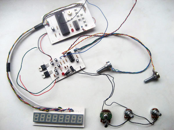
As can be seen from the above table, the three frequency ranges overlap so the full range is covered effectively. In the high frequency range it became very difficult to accurately adjust the frequencies even with a fine adjust potentiometer. I decided to use another potentiometer of smaller value in series with the existing course and fine adjust potentiometers. I implemented a course, fine and ultra fine frequency adjust using three potentiometers of 1M?, 100K? and 1K? respectively. I used pin headers for the potentiometers switches so they can be connected with wires and chassis mounted onto an instrument case.
Frequency readout using 7-segment display
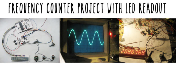
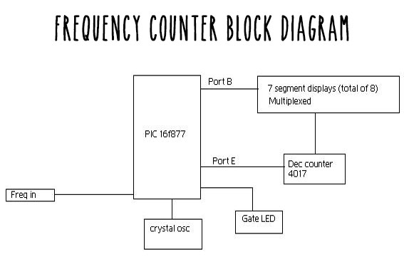
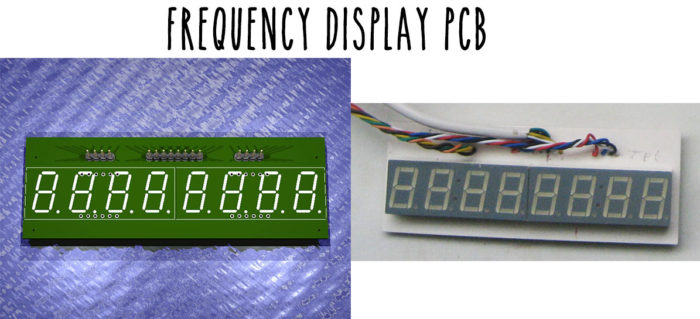
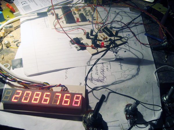
For the frequency display I used a frequency counter. I needed it to have a resolution of 1Hz and a range of up to at least 2MHz. This can be achieved with just one PIC chip with an appropriate program. The program will count the positive edges of the input signal every second (gate time = 1 second). The program will then determine the input frequency and send the value out to the display which is refreshed every second at the end of every gate time. I decided to use an LED display instead of an LCD display simply because i think it looks better and is also alot more robust and easier to read. As shown in the block diagram of the frequency counter (below) I used a 4017 decade counter to multiplex the display:
Building and testing the frequency counter / readout
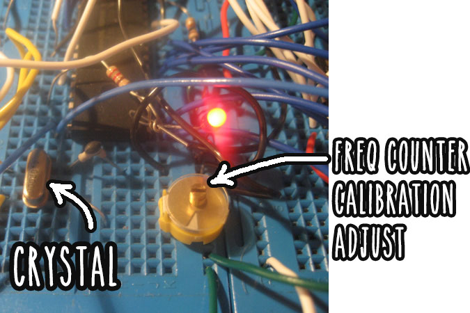
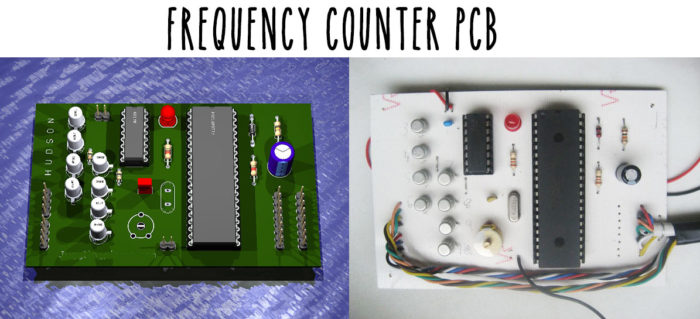
Frequency counters need to be accurate. To be able to calibrate my frequency counter I added a variable capacitor in place of the fixed capacitor in the PIC program 4MHz crystal clock. This in effect will let the gate time, which is derived from the program clock to be finely adjusted.
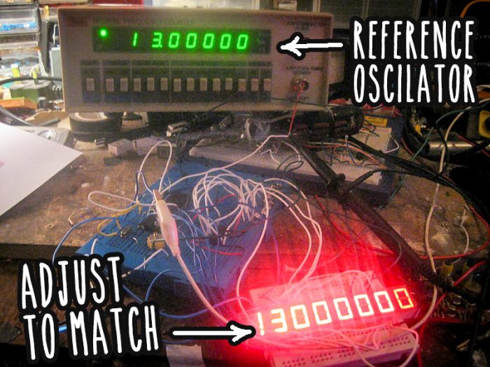
I used a very accurate OCXO (oven-controlled crystal oscillator) made for the purpose of calibrating frequency counting instruments. With a frequency of exactly 13MHz connected to the input of my frequency counter I was able to adjust my program clock using the variable capacitor until the display of my frequency counter read exactly 13MHz. See the picture below comparing my bench frequency counter and my project frequency counter both connected to the OCXO 13MHz oscillator:
Combining the frequency generator and the frequency counter
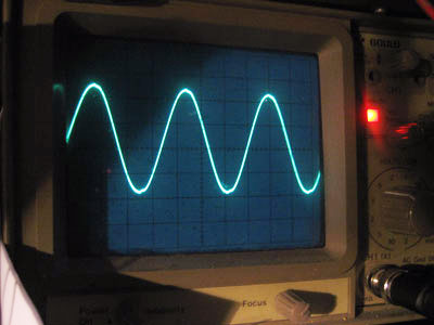
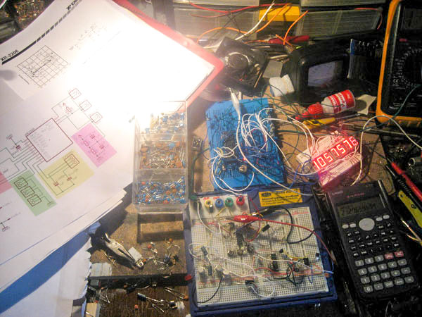
The frequency counter somehow was interfering with the frequency generator output frequency. I suspect it could have been the program clock causing the interference. To overcome the problem I heavily decoupled the power supply inputs and outputs on the power supply, suppressing any noise or oscillations. After decoupling, the waveform had no visible distortion. See below:
From breadboard to PCB
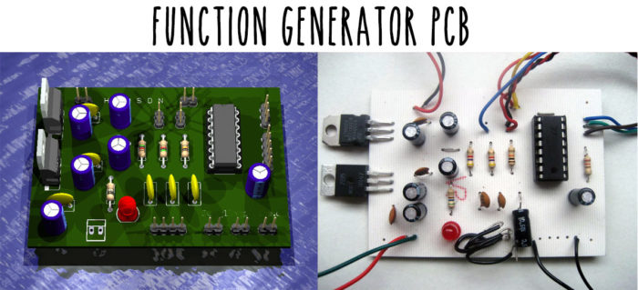
I used Eagle (Easily Applicable Graphical Layout Editor) produced by Cadsoft to design my PCBs. Once I designed the PCB layouts I used a ray-tracing package Povray (Persistence of Vision Ray tracer) to create 3D renders of my circuits that I had designed in Eagle.
The finished product consists of 3 PCBS:
1. Frequency generator:
2. Frequency counter:
3. Frequency readout display:
Full function generator with external controls
Thanks for reading. I hope this helps anyone looking to complete a project similar to this…
DAVE RUSSELL
Would love schematic daver52@live.co.uk
MasterHungSoLow
How much would you charge for the finished product?
damn
need schematic for that. cihat.ozkan91@gmail.com
Adammercer
I would love a schematic if I can please, adammercer@xtra.co.nz