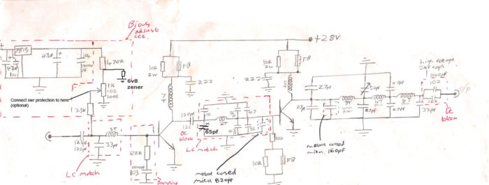

There are many non-ideal conditions that can potentially blow the transmitter, or the at least the final output transistor in the power amplifier.
The picture below shows a blown RF power transistor (SD1407). Not something you can afford to blow. The output is towards the right with the blackened DC choke coil and matching coil going to the LPF section (towards the right).
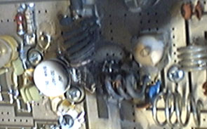
Having SWR protection probably could have saved that small fire on the circuit board and is cheap and fairly easy to implement.
Basically, the amount of RF that is going back down the line because of a bad match is rectified and represented as a small DC voltage using a diode. Once this voltage gets to a certain level (SWR too high) it will switch a transistor which will in turn shut down the bias to the PA transistor. This shutdown threshold is set and adjusted using a pot. There are a few ways of implementing SWR protection onto an RF amp but this is probably the easiest and most simple option.
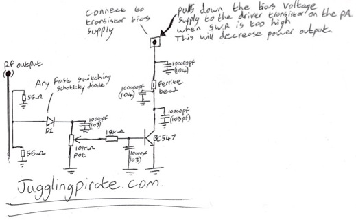
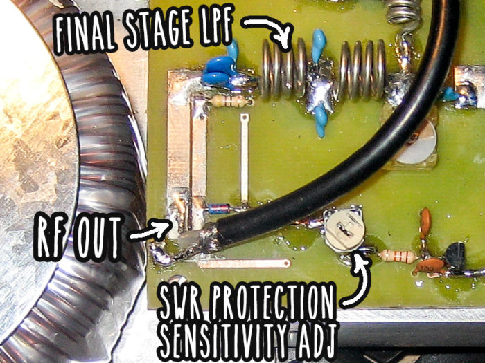
The SWR protection circuit is connected to the middle leg of the potentiometer that adjusts the bias voltage to the amp driver transistor. When the SWR is too high the SWR circuit will pull this middle leg of the pot to ground so the amp driver transistor has no bias voltage – it will output very little power.