

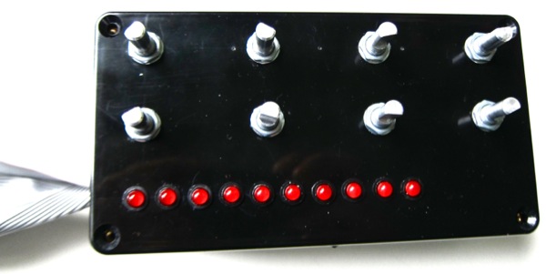
I wanted to be able to control 7 bit values in on the Altera DE2 FPGA board so i made a box with 8 quad encoders connected to the DE2 via the GPIO headers. The plan is to have the parameter associated with each encoder dynamically change depending on a selection by the user.
I picked up a few different types to play with, one with a push to make switch and two others with and without detents giving 12 and 24 pulses per revolution.
There’s a good tutorial on the Arduino site with an example written in C: http://arduino.cc/playground/Main/RotaryEncoders
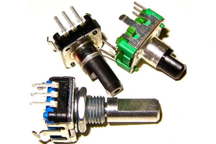
I took one apart to confirm my understanding of how they work:
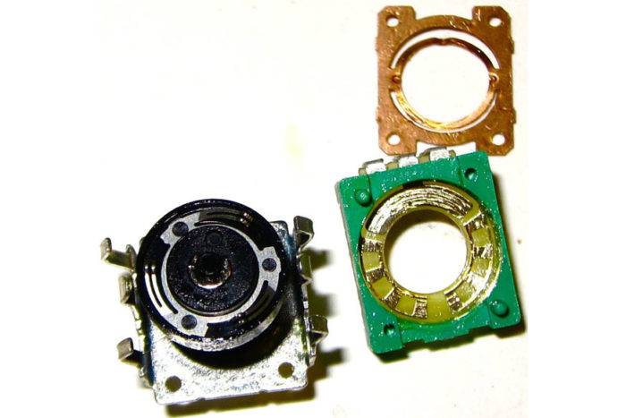
The pins are usually A, B and GND. There may also be two extra pins for a switch function (spindle can be pushed down to select different function in the code i.e course or fine adjustment resolution)
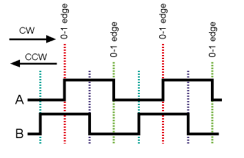
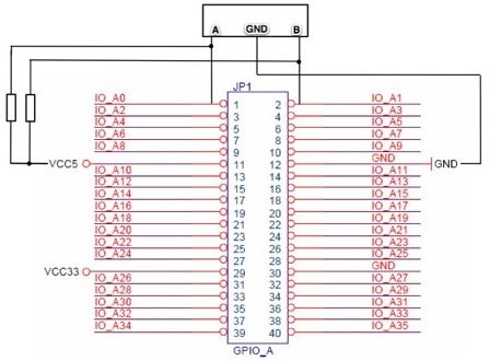
I connected the A and B channels to +5V on the GPIO header through a couple of 10k resistors and then connected these to configured inputs on the GPIO header. The middle pin of the encoder (usually GND)
VHDL code for rotary encoder
–Quadrature encoder VHDL code
–outputs a 7 bit value with min and max limits
Library IEEE;
Use IEEE.Std_Logic_1164.all;
Use IEEE.Std_Logic_unsigned.all;
Use IEEE.numeric_std.all;
Use IEEE.std_logic_arith.all;
entity rotaryencoder is port
(
CLK : in std_logic;
B : in std_logic;
A : in std_logic;
valueout : out std_logic_vector(6 downto 0) –7 bit value out
);
end rotaryencoder;
architecture struct of rotaryencoder is
signal A_INT : std_logic := ‘0’;
signal B_INT : std_logic := ‘0’;
signal A_INT_P : std_logic := ‘0’;
signal B_INT_P : std_logic := ‘0’;
–signal count : std_logic_vector(6 downto 0):=”0111111″;
signal count : integer range 0 to 2**7 := 1;
begin
main:process(CLK) is
begin
valueout <= conv_std_logic_vector(count,7);
if rising_edge(CLK) then
A_INT_p <= A_INT;
B_INT_p <= B_INT;
A_INT <= A;
B_INT <= B;
if (A_INT = ‘1’ and A_INT_P = ‘0’) then — A rising
if (B=’0′ and count /= 127) then — INC
count <= count + 1;
elsif (B=’1′ and count /= 0) then — DEC
count <= count – 1;
end if;
elsif (B_INT = ‘1’ and B_INT_P = ‘0’) then — B rising
if (A=’1′ and count /= 127) then — INC
count <= count + 1;
elsif (A=’0′ and count /= 0) then — DEC
count <= count – 1;
end if;
elsif (A_INT = ‘0’ and A_INT_P = ‘1’) then — A falling
if (B=’1′ and count /= 127) then — INC
count <= count + 1;
elsif (B=’0′ and count /= 0) then — DEC
count <= count – 1;
end if;
elsif (B_INT = ‘0’ and B_INT_P = ‘1’) then — B falling
if (A=’0′ and count /= 127) then — INC
count <= count + 1;
elsif (A=’1′ and count /= 0) then — DEC
count <= count – 1;
end if;
else
count<= count;
end if;
end if;
end process;
end struct;
Peter
Hello!
May I ask you what is the difference between
signal count : std_logic_vector(6 downto 0):=”0111111″;
and
signal count : integer range 0 to 2**7 := 1;
???
If i would like to be able to control 32 bit values is it enough to change
to signal count : std_logic_vector(31 downto 0):=”01111…11″; #(31 ones inside ” “)
and each 127 like here
if (B=’0′ and count /= 127) then — INC
change to 2^32-1 ?
May it work?
Peter